If you use software to create your P&IDs, there are some basic steps to follow:
- Create and check an equipment list. Use the symbols within the library after you’re sure of your list.
- Connect pipes and equipment, then review the details with a trusted colleague. Walk through the process several times and search for inefficiencies.
- Share with collaborators.
For more details and how-to, go to the P&ID Tutorial.
Organization fundamentals of P&ID
As a keystone document, the P&ID should be organized in a logical progression. While many—or most—companies set their own standards for P&ID organization, it can be thought of as chapters of a book or scenes from a movie that interconnect to tell your engineering process story. It should provide a concise and easy-to-understand illustration of all the equipment to be included in the process flow, alert information around hazard, safeguards and potential faults so that errors can be minimized or eliminated. It will help support the development of operating and maintenance procedures. As a storyboard of the process, it’s a way to see that changes can be made safely and effectively using Management of Change.
Different types of P&ID diagrams
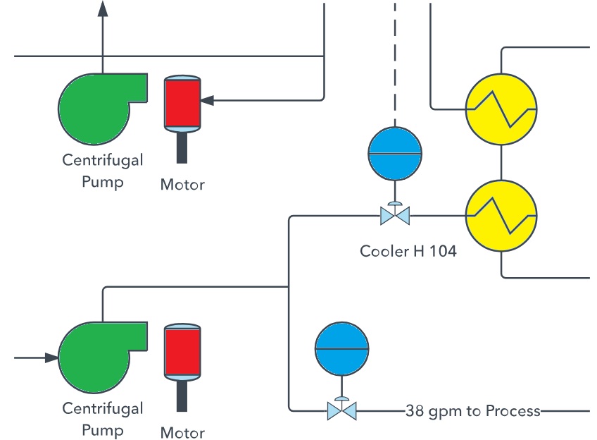
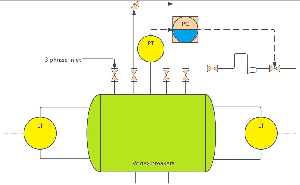
There are as many different styles and types of diagrams as there are companies and products. Here are two examples:

This example shows a fluid flow system and defines mechanical and design configurations that are in place.

A P&ID of 3-phase separator vessels, which are components used in the oil and gas industry to separate various liquids that flow from wells.

